Subtitles & vocabulary
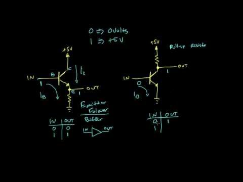
Comparing the buffer and inverter circuits | Digital electronics (10 of 10)
00
林宜悉 posted on 2020/03/27Save
Video vocabulary

assume
US /əˈsum/
・
UK /ə'sju:m/
- Transitive Verb
- To act in a false manner to mislead others
- To believe, based on the evidence; suppose
A2TOEIC
More process
US /ˈprɑsˌɛs, ˈproˌsɛs/
・
UK /prə'ses/
- Transitive Verb
- To organize and use data in a computer
- To deal with official forms in the way required
- Noun (Countable/Uncountable)
- Dealing with official forms in the way required
- Set of changes that occur slowly and naturally
A2TOEIC
More boost
US /bust/
・
UK /bu:st/
- Transitive Verb
- To increase something; to make something better
- To push someone or something up from beneath them
- Noun (Countable/Uncountable)
- An increase in something
B1TOEIC
More basically
US /ˈbesɪkəli,-kli/
・
UK /ˈbeɪsɪkli/
- Adverb
- Used before you explain something simply, clearly
- In essence; when you consider the most important aspects of something.
A2
More Use Energy
Unlock Vocabulary
Unlock pronunciation, explanations, and filters

