Subtitles & vocabulary
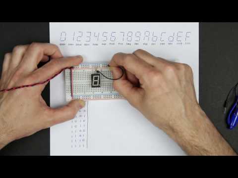
Designing a 7-segment hex decoder
00
林宜悉 posted on 2020/03/27Save
Video vocabulary

sort
US /sɔrt/
・
UK /sɔ:t/
- Transitive Verb
- To organize things by putting them into groups
- To deal with things in an organized way
- Noun
- Group or class of similar things or people
A1TOEIC
More essentially
US /ɪˈsenʃəli/
・
UK /ɪˈsenʃəli/
- Adverb
- Basically; (said when stating the basic facts)
- Used to emphasize the basic truth or fact of a situation.
A2
More demonstrate
US /ˈdɛmənˌstret/
・
UK /'demənstreɪt/
- Verb (Transitive/Intransitive)
- To display a feeling or ability openly
- To protest about something often as a group
A2TOEIC
More compliment
US /ˈkɑmpləmənt/
・
UK /'kɒmplɪmənt/
- Noun (Countable/Uncountable)
- Remark saying someone looks nice, plays well, etc.
- A formal expression of respect or admiration.
- Transitive Verb
- To say someone looks nice, plays well, etc.
B2
More Use Energy
Unlock Vocabulary
Unlock pronunciation, explanations, and filters

